|
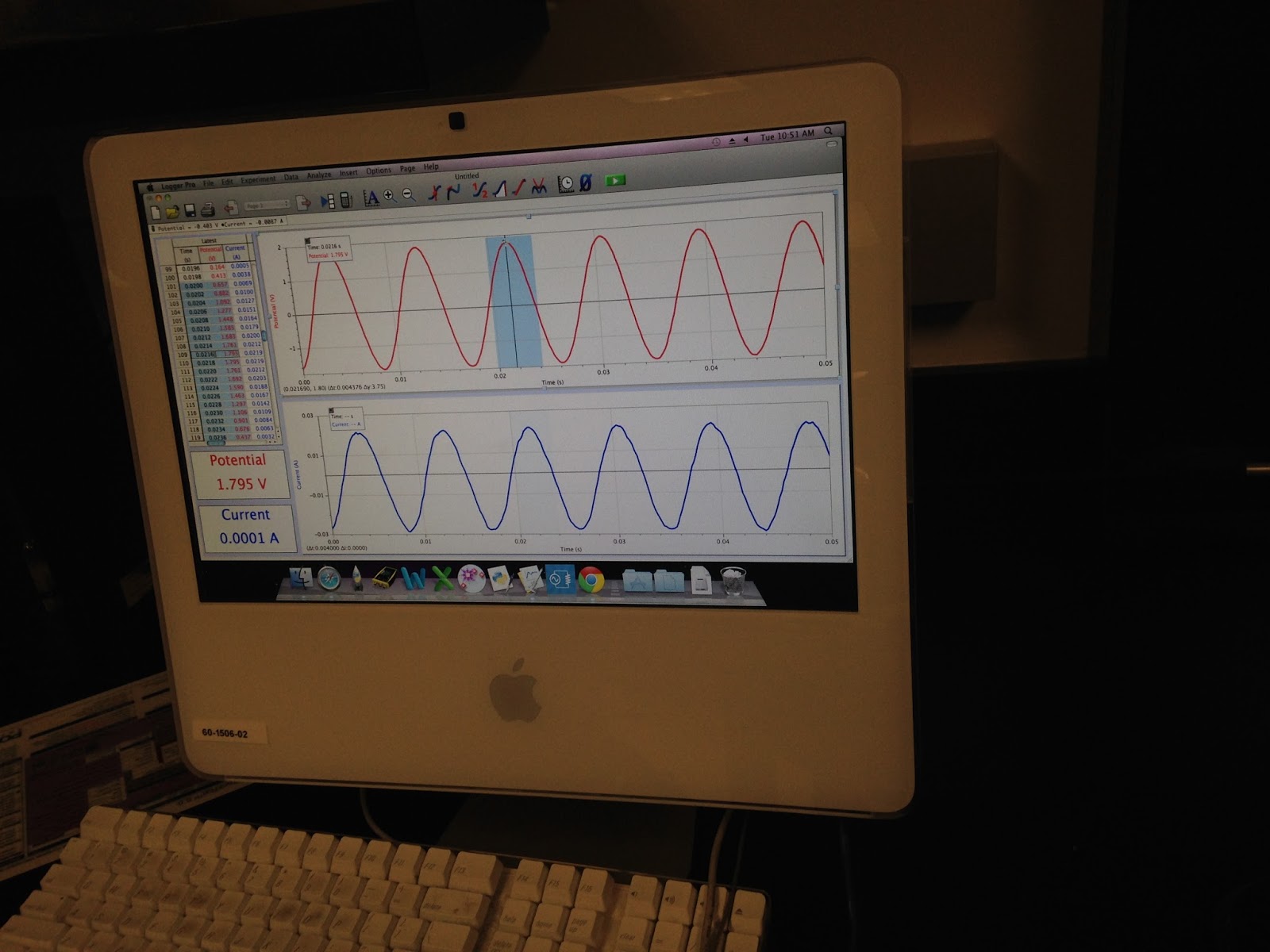
| This is the graph of the voltages and current in an ac circuit containing a resistor and a capacitor as functions of time. |
 |
| Here is our table of values for the capacitive reactance as well as the impedence of a circuit with a resistor and a capacitor. By raising the frequency, we effectively increase the impedence, allowing for a greater potential in the circuit. |
 |
| The resonating frequency of an alternating current is given in the top left corner. At three thousand hertz, the rms value for current in this circuit is 2.06 A. To find the power dissipated, we can ignore the inductor and the capacitor, and treat the circuit as if there is only a resistor present. In this circuit the power dissipated is 42.6 W. |
 |
| In this image we can see that in this ac-circuit, the voltage leads the current by 90 degrees. |
 |
| Here we have a voltage generator, resistor, ammeter, capacitor, and inductor all connected in series. On the generator, we change the frequency in order to find when it has its maximum current. |
 |
| We predicted that the maximum current would occur at 90.6 hertz, when in fact maximum current occurred at 112 hertz. Our experimental error was 19.1%. |
Conclusion: The current is maximum in an AC-Circuit when the capacitive and inductive impedences are equal. The voltage across the inductor leads the current by 90 degrees, while the voltage across the capacitor lags the current by 90 degrees. The voltage across the resistor is in phase with the current.