Thursday, May 21, 2015

Electromagnetic Induction


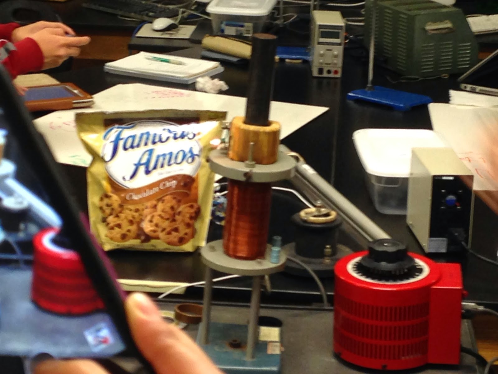
The two photos above summarize some of the key characteristics of an induced emf in a conducting loop.

A current carrying loop placed inside a magnetic field directed towards the top of the board witnesses a magnetic force. With current directed out of the plane of the page or in, the force is directed to the left or right, respectively. 

In an induced motional EMF, the magnetic flux changes because of the changing area vector, which changes with respect to time. In a slidewire generator, the velocity of the sliding wire directly affects the rate of change of magnetic flux. Since the induced EMF equal BLv, and IR, we can easily solve for I.

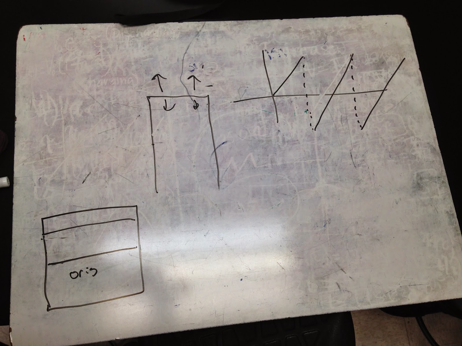
These are various relationships between several elements in a circuit with an inductor (L) and a capacitor (C)

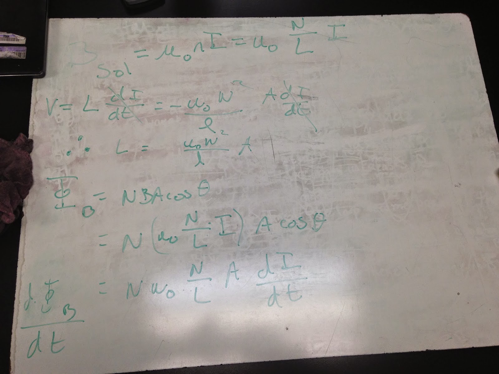
The self inductance of a solenoid (L) is equal to the product of 4*pi*10^-7 (mu-knot), and the current running through the solenoid, the inverse of the length of the solenoid, the cross-sectional area of the solenoid, and the square of the number of loops in the solenoid.

The circuit above consist of a capacitor, a source of EMF, and a resistor. The circuit on the bottom has a source of emf, a resistor, and an inductor. The inductor is meant to oppose any rapid changes in current, forming an induced EMF in the direction that opposes the change in current.

As current initially starts flowing in a circuit with an inductor, it takes time for the current to build up to its maximum magnitude, eventually leveling off as time goes on. 


Inductors of higher magnitude requires greater time for a current to reach its maximum level than an inductor of lower magnitude. Just like capacitors, inductors have a time constant that determines the amount of time it will take for a circuit with an inductor to reach a maximum and minimum time rate of change in charge flow.

Force due to Magnetic Fields and Currents

This is a depiction of two wires a current in the same direction. The magnetic field on the left wire due to the right points out of the board. The magnetic field on the right wire due to the left wire points into the board. This results in an attractive force between the two conductors.

Rotating a sensor around the the axis of results in a sinusoidal graph of the magnetic field.

In this experiment, we would move a bar magnet in and out of the loop of wire to see the effects that the motion had on the current. The speed at which we moved the magnet effected the current. Also, the more turns in the coil, the stronger the current.

The flux of a magnetic field through a surface.


In this experiment, we ran a current which varied over time. This created a change in the magnetic flux over time. When a toroidal solenoid with a light was placed over the rod, we see the light turn on. The changing flux induces an electric field in the solenoid. When a charge moves around the solenoid, the work done on it equals the magnitude of charge multiplied by the induced EMF. This induced emf is equal to the line integral of the electric field dotted with the total path. 

All of these factors effect the induced EMF in the situation above.


The induced emf in this situation depends only on the varying magnetic field. They magnetic field changes due the to rotation of the magnet. Taking the time derivative of the magnetic field, we end up the the formula for an induced EMF at the bottom of the board. Also, the large depiction illustrates Lenzs Law. A counter clockwise current in the coil of wires creates an upward magnetic pole. Increasing the current, increases the magnetic field, which in effect creates a current in the conductor in the opposite direction. This in effect creates a magnetic field in the opposite direction. The direction of the magnetic induction acts to oppose the cause of the effect.

When the flux is at its maximum, the instantaneous rate of change is zero, and the induced EMF is zero. When the flux is changing most rapidly (as the sinusoidal graph passes through the x-axis), the Induced EMF is at its max.

Wednesday, May 20, 2015

Magnetic Fields Due to Current

In a magnet, all the magnetic dipoles created by the motion of electrons around their nucleus are aligned. The direction of this moment the direction of the magnetic field. In objects that are not magnetized, the moments are randomly oriented. Heating or exerting a very large impulse on the magnet can knock the aligned magnetic dipoles out of alignment.


In a current carrying loop, a magnetic moment is produced perpendicular to the plane of the loop. This magnetic moment (mu) is equal to the current multiplied by the area. When the loop is introduced to an external electric field, the field tends to rotate the loop so that the magnetic moment and the external field are parallel. If there are multiple loops, the total magnetic moment is the product of the current, the area of the loop, and the number of loops. In the equation, theta is the angle between the magnetic moment and the magnetic field.
Here is a basic motor. It is a current carrying loop (rotor) in a magnetic field. One end the rotor is half covered in an insulated finish, and the other end is fully exposed. When plane of the rotor is perpendicular to the magnet, the rotor spins so the that the magnetic moment is parallel to the magnetic field. At this point, current stops running through the rotor (due to the half covered end of the wire), and there is no torque to keep the rotor in this position. The momentum gained from the initial 90 degree rotation allows the rotor to keep spinning. Then, both ends are now fully in contact with the wires, allowing a current to flow through again, reproducing a magnetic torque. This cycle continues.

Placing the compasses around the current carrying rod, we see that the needles all point in a circle around the rod. Wrapping our fingers around the rod with our thumbs pointing in the direction of the current, we determine the direction of the field by the direction in which our fingers curl. The magnetic field created forms circles in a plane perpendicular to the direction of the current. 
A current flowing towards you creates a clockwise magnetic field around it, and a current directed away from you creates a counterclockwise field. Amperes law states that the total current enclosed by a surface is equal to the line integral  around the closed surface. We also derived an expression for the magnetic field produced by a current. 

Magnetic Fields

When placing a compass at different positions around the magnet, we saw the the compass needle pointed in different directions at each location. The arrows drawn are the direction the arrows pointed at each location.

The magnetic field of a magnetized object points from the north end of the object to the south pole. Enclosing the object in a gaussian sphere results in a zero net flux.

The magnetic force created on a moving charged particle in a magnetic field is the cross product of the qv x B, where q is the charge of the particle, v is the velocity vector, and B is the magnetic field vector. For negatively charge objects, the direction of the force is opposite to that of the right hand rule. When the object is moving in a direction parallel to the field, it experiences no magnetic force.

The magnitude of the magnetic force is the equal to the product of the charge, the magnitude of the velocity vector perpendicular to the magnetic field, and the magnitude of the magnetic field. The units of the a magnetic field is N/Am, or the Tesla (T).


Here we calculated the magnetic force vector on a proton in motion. This is allows us to see the acceleration the proton experiences in the magnetic field.

When a charge particle moves perpendicular to a uniform magnetic field, the magnetic force is always perpendicular to its velocity. Therefore, the magnitude of the velocity never changes, and it experiences a radial acceleration of v^2/R. If the particle is not moving perpendicular to the the field. then the component of the velocity parallel to the mangetic field is constant, and the object path of motion traces out a helix.

The angular frequency of the charged particle moving in the magnetic field is equal to v/R. Substituting our value for R from the previous picture allows the determine the angular frequency can be represented by qB/m. (q-charge; B-magnetic field; m-mass).

We see here that the product q*v can be represented as the product of the length of the wire the a current runs along. 

Here is a depiction of two loops of wire with a current running through it. When a magnetic field flows parallel to the plane of a loop, the net force on the loop is zero, but a net torque is exerted on the loop. When field runs perpendicular to the plane of the loop, there is zero net torque and zero net force. 
Here is a current carrying wire inside a magnetic field. The field caused the wire to jump toward us. When a current carrying loop was inserted into the field, we saw that is rotated as a result of the torques experienced by the loop.


For this assignment, we need to find the total force on this current carrying half loop. All the x components of the magnetic force cancel each other out, so the only force component that matters is the y-component of force.
The y component of force equals I*L*B*sin(theta). Breaking the half circle up into 15 segments provides a turn of 12 degrees for each segment. The the length L is equal to the radius multiplied the change in degrees. F=I*R*d(theta)*B*sin(theta).

Oscilloscope


This is an oscilloscope. Inside is a cathode ray tube (CRT). The CRT contains a magnetic field and it shoots a beam of electrons at the screen, creating a glow on impact. The direction that the electrons travel towards the beam changes in response to varying voltages.


With not battery attached. the beam creates a steady line. When a battery is a attached, an electric field is created, the direction that the beam of electrons travel in changes in response to the electric force. We predicted correctly that the line created by the beam will jump to a higher level. 
When we attach a function generator to a speaker, we see that increasing the frequency of the function creates a higher pitched sound, and increasing the voltage increases the volume.

The sin function setting on the function generator creates a sine function on the screen.

Setting the function generator to the square setting produces this image on the oscilloscope screen.
When analyzing the current from a DC output source in AC mode on the oscilloscope, we see that the output is not as direct as it should be. We see that it takes a little while for the voltage supplied to the electron beam to level off.

This is the image produced by an alternating current.
This is the image created when there is both an AC current and a voltage introduced from the function generator. Adjusting the frequency of the function from the generator alters the movement of these sin functions. The frequency slows to a minimum at every 60 Hz.
The following pictures were answers to the activities from the book that we had to do.
These are our observations from every possible combination of voltages that could be delivered to the oscilloscope from the mystery box.