 This is an oscilloscope. Inside is a cathode ray tube (CRT). The CRT contains a magnetic field and it shoots a beam of electrons at the screen, creating a glow on impact. The direction that the electrons travel towards the beam changes in response to varying voltages. 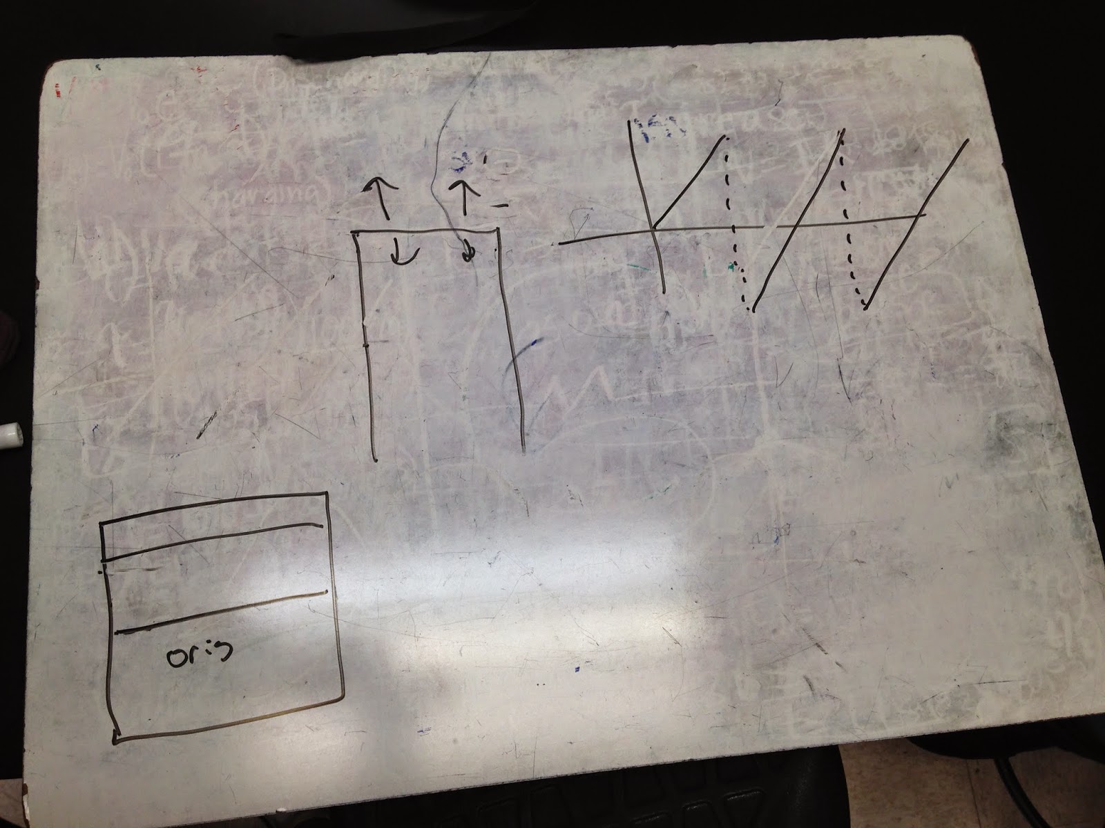 |
| With not battery attached. the beam creates a steady line. When a battery is a attached, an electric field is created, the direction that the beam of electrons travel in changes in response to the electric force. We predicted correctly that the line created by the beam will jump to a higher level. |
 |
| When we attach a function generator to a speaker, we see that increasing the frequency of the function creates a higher pitched sound, and increasing the voltage increases the volume. |
 |
| The sin function setting on the function generator creates a sine function on the screen. |
 |
| Setting the function generator to the square setting produces this image on the oscilloscope screen. |
 |
| When analyzing the current from a DC output source in AC mode on the oscilloscope, we see that the output is not as direct as it should be. We see that it takes a little while for the voltage supplied to the electron beam to level off. |
 |
| This is the image produced by an alternating current. |
 |
| This is the image created when there is both an AC current and a voltage introduced from the function generator. Adjusting the frequency of the function from the generator alters the movement of these sin functions. The frequency slows to a minimum at every 60 Hz. |


 |
| The following pictures were answers to the activities from the book that we had to do. |
 |
| These are our observations from every possible combination of voltages that could be delivered to the oscilloscope from the mystery box. |
No comments:
Post a Comment