Thursday, May 21, 2015

Electromagnetic Induction


The two photos above summarize some of the key characteristics of an induced emf in a conducting loop.

A current carrying loop placed inside a magnetic field directed towards the top of the board witnesses a magnetic force. With current directed out of the plane of the page or in, the force is directed to the left or right, respectively. 

In an induced motional EMF, the magnetic flux changes because of the changing area vector, which changes with respect to time. In a slidewire generator, the velocity of the sliding wire directly affects the rate of change of magnetic flux. Since the induced EMF equal BLv, and IR, we can easily solve for I.

These are various relationships between several elements in a circuit with an inductor (L) and a capacitor (C)

The self inductance of a solenoid (L) is equal to the product of 4*pi*10^-7 (mu-knot), and the current running through the solenoid, the inverse of the length of the solenoid, the cross-sectional area of the solenoid, and the square of the number of loops in the solenoid.

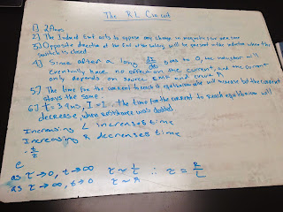
The circuit above consist of a capacitor, a source of EMF, and a resistor. The circuit on the bottom has a source of emf, a resistor, and an inductor. The inductor is meant to oppose any rapid changes in current, forming an induced EMF in the direction that opposes the change in current.

As current initially starts flowing in a circuit with an inductor, it takes time for the current to build up to its maximum magnitude, eventually leveling off as time goes on. 


Inductors of higher magnitude requires greater time for a current to reach its maximum level than an inductor of lower magnitude. Just like capacitors, inductors have a time constant that determines the amount of time it will take for a circuit with an inductor to reach a maximum and minimum time rate of change in charge flow.

No comments:

Post a Comment